Lighting and low powered ancillary services - 110V or 220V.
Portable equipments- 55V or 24V.
Bow thrusters - 3.3KV
Batteries- 12V or 24 DC
Power Management System [PMS]:
An
electrical power management system is to ensure continuous availability
of electrical power and to avoid blackout.Main switch board is
associated with this.
PMS is for
- ship’s operation mode selection - harbour mode, manoeuvering mode, at sea mode
- generator management during black out
- load dependent starting and stopping of generators with all safeties
- autosynchronistaion, load sharing and frequency control
- preferential trips, various protection systems, load inhibition of heavy consumers
Electrical Diagrams:
- block diagrams - simplified form, shows interrelationship of elements in system
- system diagrams - illustrates ways of operating systems,shows main features
- circuit diagram - shows in full the functioning of a circuit, essential tool for troubleshooting
- wiring
diagram - shows detailed connection between components , mainly to
instruct wiring installers how to construct and connect
Electrical Safety:
To work on ship’s electrical system -
- get to know / study ship’s electrical system
- operate and maintain as per manufacturers instruction
- ensure all guards, cover and doors are fixed properly
- inform OOW before shutting down machinery
- Risk assessment and work permit to be taken
- confirm circuit is dead[ by voltage tester]
- LOTO - lock out & tag out
Electrical Shock:
- A shock current as low as 15mA DC or AC is fatal
- body
resistance goes down as applied voltage goes up - typical dry full
contact body resistance is 5000ohm at 25V, 2000ohm at 250V
- voltages
60V and below is safe for portable hand use. 24V portable hand lamps
are generally used for confined spaces. special step down transformers
are used with portable equipments for which secondary winding is centre
tapped to earth [splits winding into two sides with each having only 55V
with respect to earth for a 440-110V stepdown transformer.55V is still
fatal but better than full 110V]
Welding equipment safe practices:
- insulate yourself from work piece and return cable by wearing dry insulated clothes
- use rubber sole shoes and gloves in good condition
- use good lighting
- wet working condition to be avoided, even person’s perspiration can lower body resistance
- terminals on welding machine to be tight and clean
- do not use damaged / worn cables and lugs
- do not touch return line as it carries as much current as welding cable
- there should be good earthing arrangement made close to the job
- avoid using hull as return conductor as this will circulate current in hull through parts like bearings causing damage.
- do not wrap cables carrying current around body
- electrodes should not be inserted into a live holder
- use fully insulated electrode holder
- do not touch energized electrode with bare hands
- handtools and welding equipment must be inspected periodically[once in 3months]
- ELCBs to be installed in extension boards for providing temporary power supply
- check condition of quick detachable connection of 1.5metres, insulated wheels of machine, insulation of line connection
Insulation Resistance:
Insulation
prevents leaking away of current from conductors and prevents contact
with live wires.Insulation resistance is measured between
- conductor & earth
- conductors
Surface
deposits reduce insulation resistance.Flow of leakage current through
surface deposits [dirt,oil,moisture] on insulation is called tracking.Insulation resistance is also affected by creepage and clearance between terminals.
Equipments
must be maintained clean to prevent tracking and to maintain high value
of insulation resistance.Insulation is also affected by
humidity,temperature,electrical and mechanical
stress,vibration,chemical,oil,dirt,grease and ofcourse aging.All marine
equipments are constructed to work satisfactorily at a temperature below
45degree celsius.
Various classes of insulation at which they are safe to operate :
These are steady surface temperature measured with equipment stopped and no flow of cooling air. Hotspot temperature
of 105degrees-classA,130degrees-classB is accepted as normal
temperature at centre of coils and windings with surface temperature as
mentioned in table.Machines operated continously with above hotspot
temperature has life expectancy of 15 to 20yrs.However every 10degree rise of hotspot temperature reduce life by half.
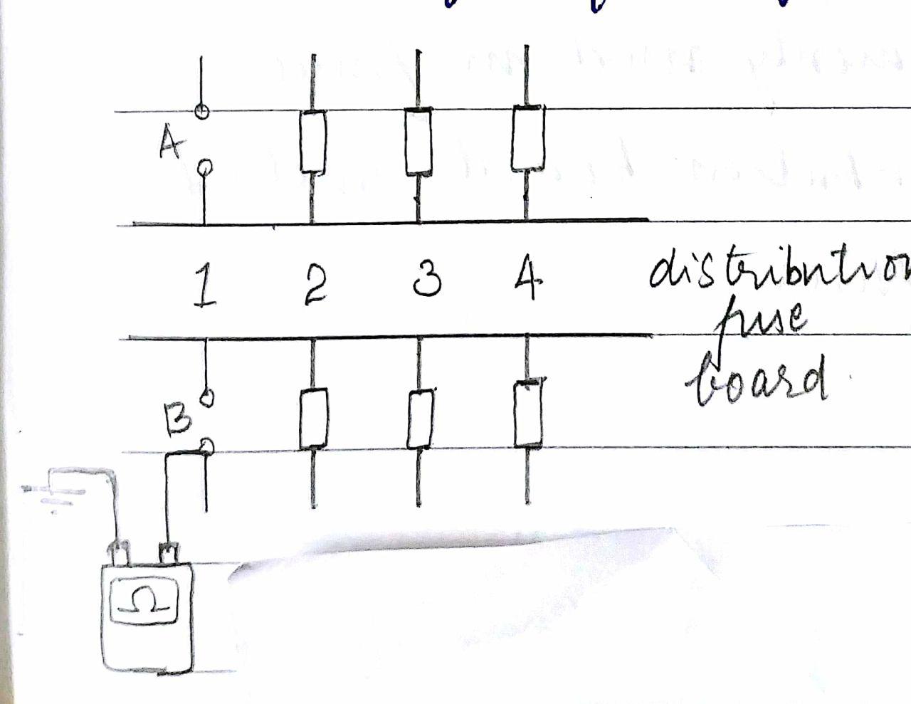
Insulation testing: IR tester is used
Resistance is measured between
- conductor and earth
- conductors
500V DC producing megger is used. In H.V ships test voltage produced is at the range of 5000V and above.
To
prove basic operation switch to megaohm , short two probes together and
hit test button.Pointer should indicate around 0ohm.Before testing,
equipment must be LOTO. To test if equipment is live IR tester is to be
switched to megohm and probes are connected to pairs of terminal. Do not
press hit button. Meter will now indicate if the circuit is live or
not.
For an IR test of a 3 phase machine 3 readings are measured as U-V, V-W, U-W.
Phase to earth is also measured as U-E,V-E,W-E.
Insulation
becomes more leaky at high temperature. So testing while at its working
temperature shows realistic value.Regular recording of the test gives a
trend which if downwards indicates impending trouble.
Continuity Testing: IR Tester/Multimeter is used
- Prove correct operation by shorting probes and hitting test button.Should show no resistance.
- Equipment to be LOTO
- Prove whether equipment is dead
- Switch instrument to ohm or continuity
- Connect probes to circuit and hit test button
- Check indication of pointer on scale
Measuring AC Voltage:Multimeter is used
- Set selector switch to appropriate voltage range
- Hold
insulated probes and connect the tips of the probe to a known live
voltage source like AC 220V socket and verify working of meter
- When not aware of the voltage set it to maximum range
- Connect the probes across the point to be measured and note the value
Measuring current using clamp meter:
This
equipment is used against live circuit, atmost care is to be
taken.Meter must be certified and be capable to measure current in that
circuit.If not aware of the range then set it to maximum.
Hold meter over the conductor by pressing the button to open the spring loaded clamp and check reading.
Latest clampmeters measures power and power factor too.For multicore cables it shows zero as net flux is zero.
Live Line Testers
are simple devices to check whether or not a voltage exist at
terminals.They are of various types-some light up,some make noise or
operate LED etc.